The USB port on my Seaboard RISE worked at an angle. Then only at a stranger angle. Then Audio MIDI Setup showed it for half a second and dropped it, and then nothing.
Bluetooth kept dropping out as well.
The jack wasn’t broken. Three of the four traces leaving it were.
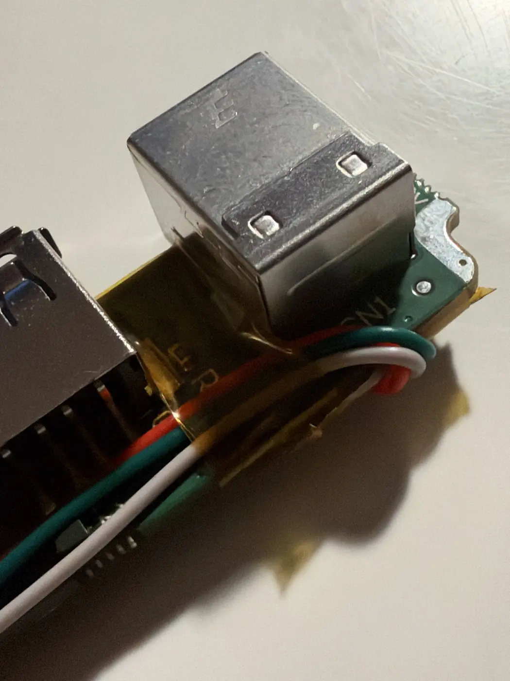
What actually breaks
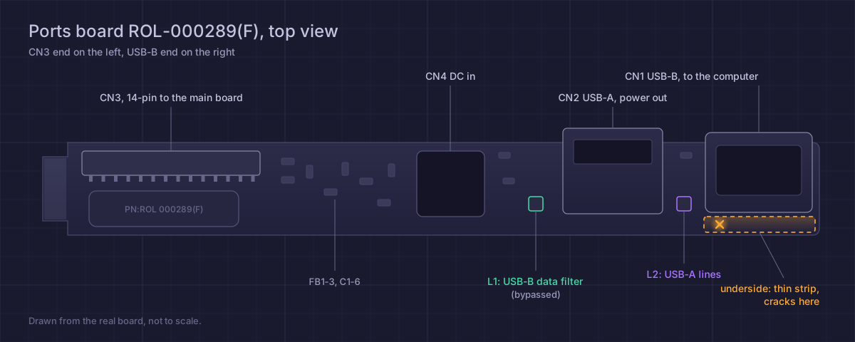
The jack sits in a slot cut into the ports board. A thin strip beside the slot, a few millimetres wide, carries all four of its traces. Every levered plug flexes it. The solder mask crazes, then the copper snaps at the necks of the pads.
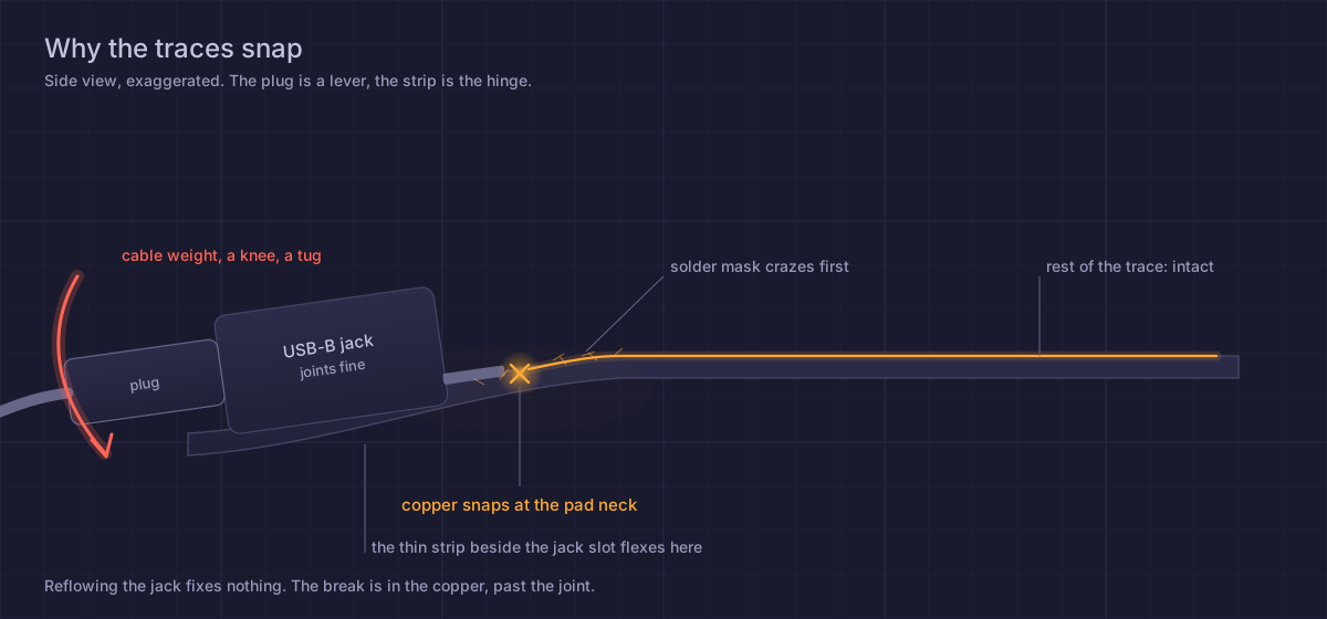
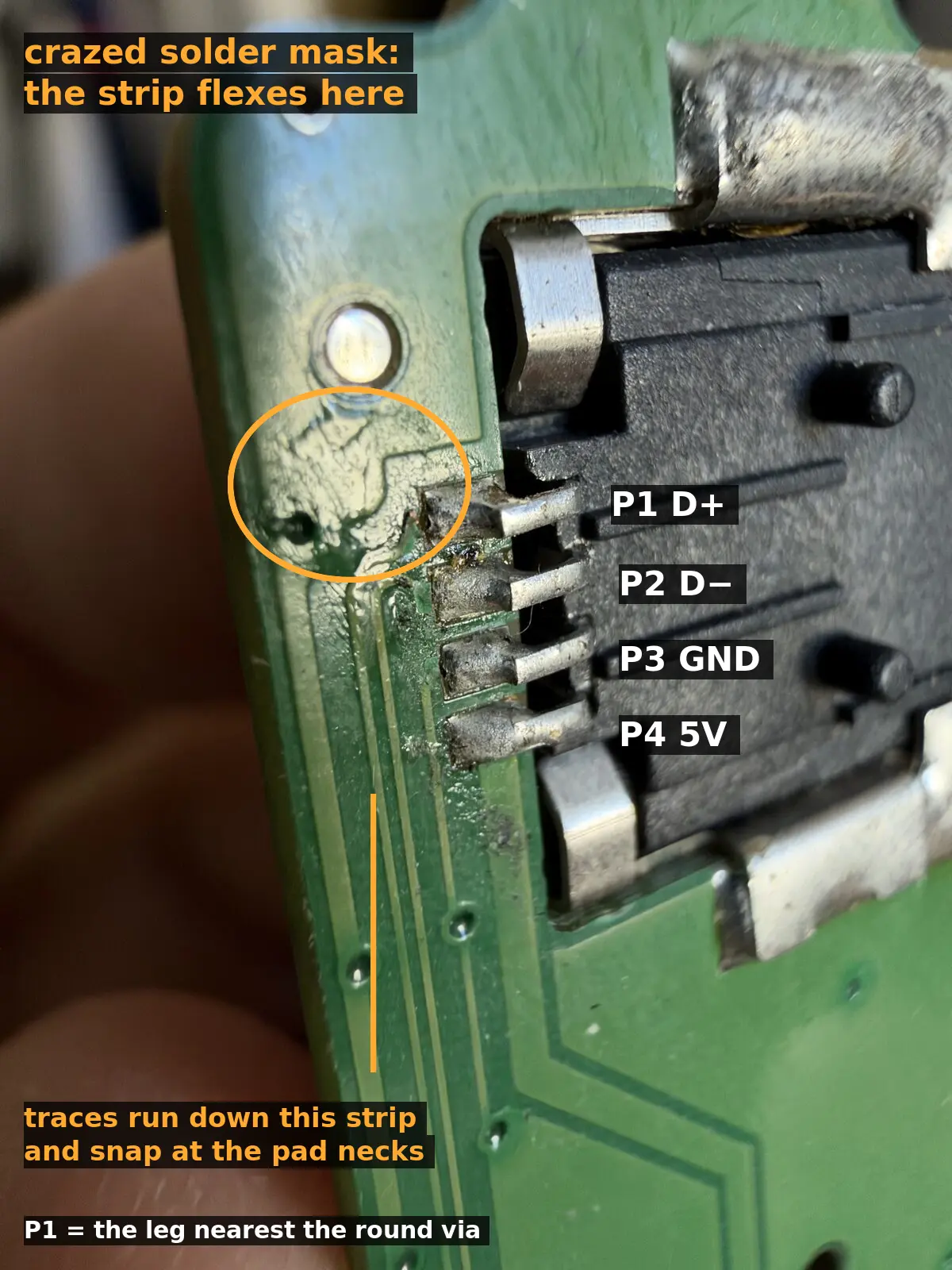
Joints clean, 5.23 V on the jack’s 5 V leg with a cable in. Reflowing does nothing. A new jack lands on the same cracked copper.
Rule out the cable first. Mine worked fine with an MPK249.
ROLI’s USB repair procedure covers getting the ports board out. Unplug its harness at the main board end first.
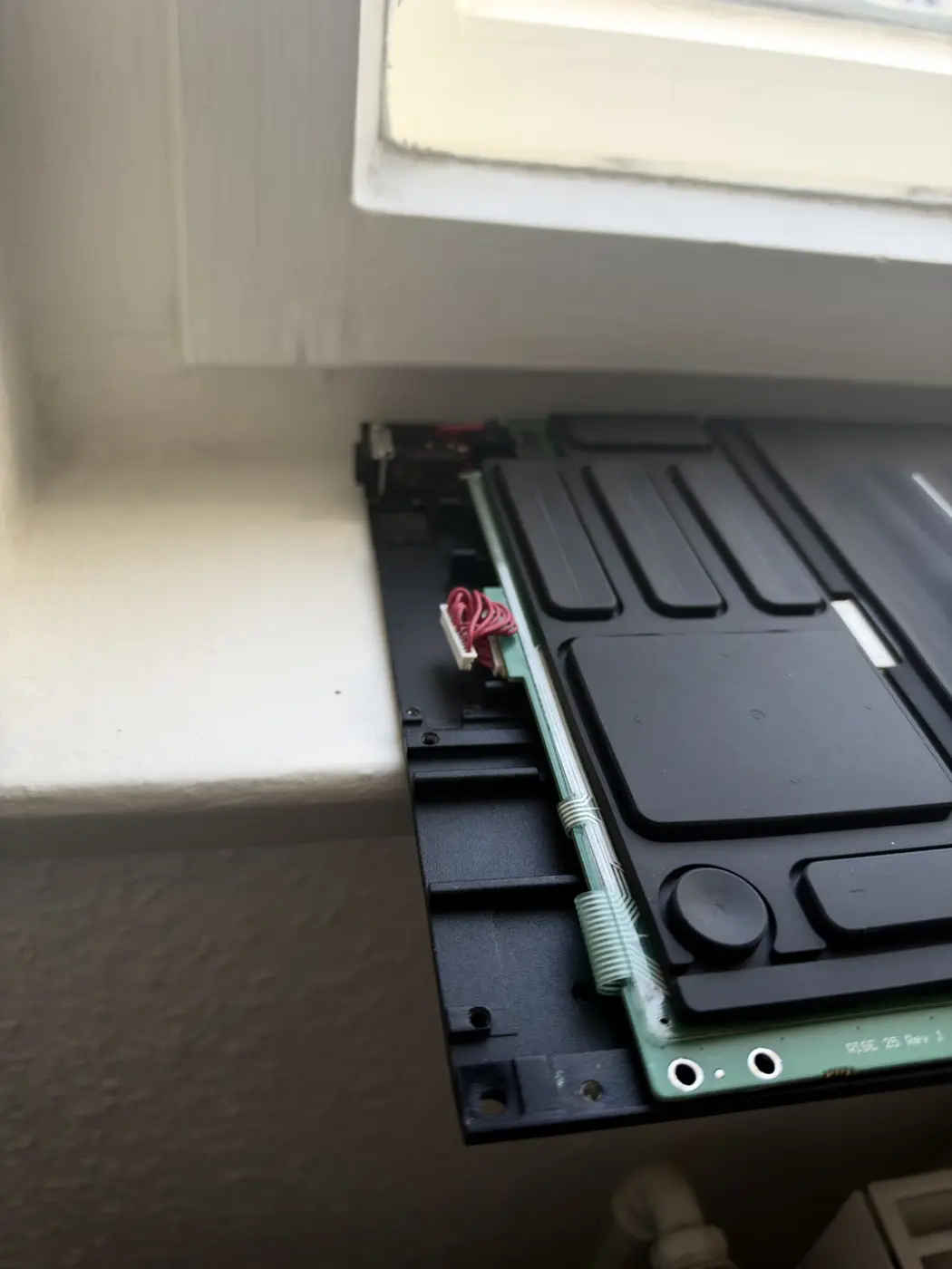
Mine is ROL-000289(F).
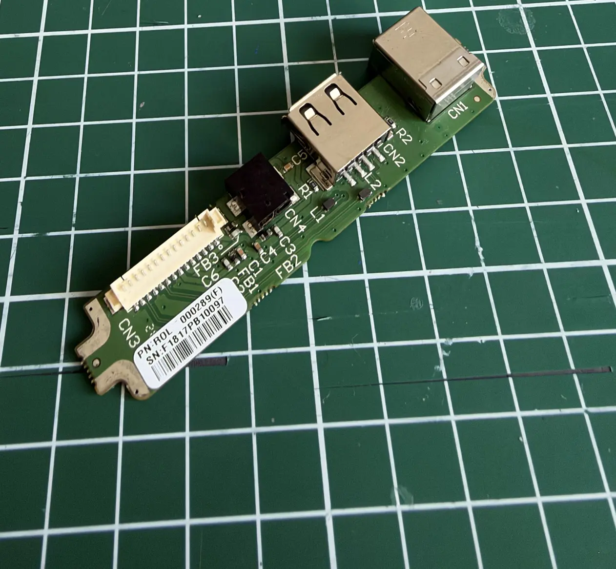
Find the break
Continuity mode. One probe on a jack leg, the other on CN3, the 14-pin connector from the ports board to the main board.
CN3 numbered from the USB-B end:
| CN3 | Net |
|---|---|
| 3, 4, 8, 11, 14 | GND |
| 5, 6 | USB-A 5 V out |
| 7 | USB-B 5 V |
| 9 | USB-B D+ |
| 10 | USB-B D− |
| 12, 13 | USB-A lines (power only per ROLI, probably charge signalling) |
On mine, the 5 V leg still beeped through to CN3 7. The other three beeped to nothing.
The data lines pass through a small filter, L1, on the way to CN3 9 and 10. Its pads are tiny. Skip it. USB on the RISE runs at full speed, 12 Mbit/s, and a few centimetres of wire straight to CN3 is fine at that rate.
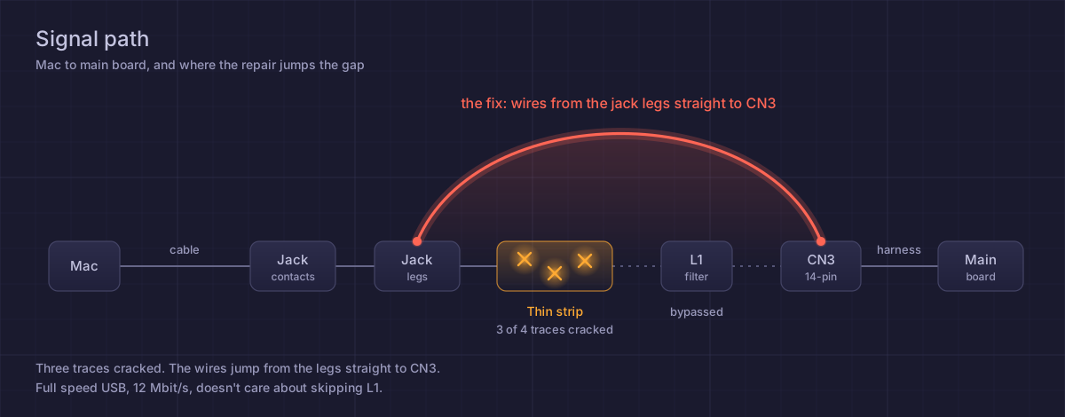
The leg order is not the USB order
This is the part that cost me an evening.
USB-B pins are numbered 1 VBUS, 2 D−, 3 D+, 4 GND. The legs on this jack don’t come out in that order. Wire them as if they do and you tie a data line to ground. The RISE still powers up. The Mac never sees it.
Measure it through a cable. Plug one into the jack and beep the contacts of the USB-A plug at the far end against the jack legs. P1 is the leg nearest the round via.
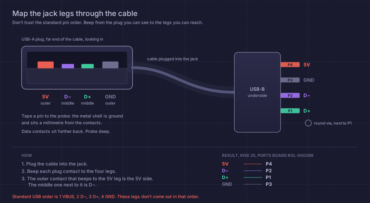
The plug’s metal shell is ground and sits a millimetre from the contacts, so a probe tip touches both and everything beeps to ground. Tape a sewing pin to the probe. The data contacts are shorter than the power ones, set back so power connects first. Probe deeper.
Wiring
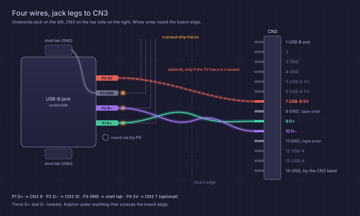
- P1 D+ → CN3 9
- P2 D− → CN3 10
- P3 GND → the jack’s shell tab. Any ground works. The shell tab is right there.
- P4 5 V → CN3 7, only if that trace is also cracked. Mine wasn’t.
Wires go on the jack legs on the underside, wrap round the board edge, and land on the toes of the CN3 legs on top, past the plastic.
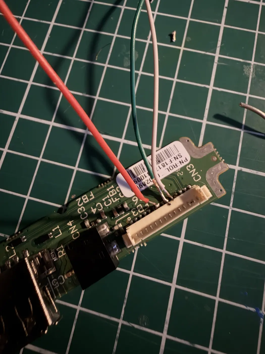
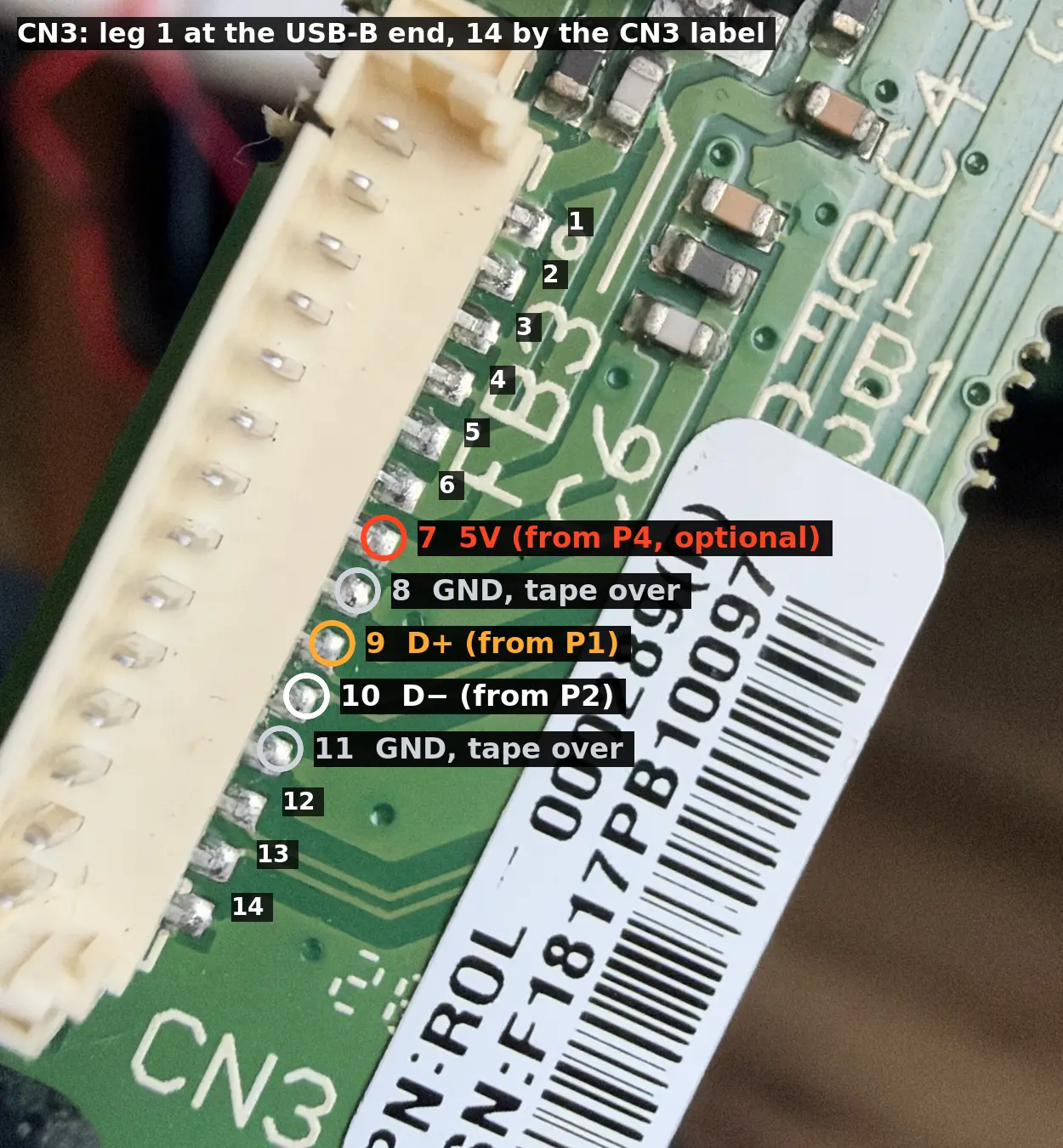
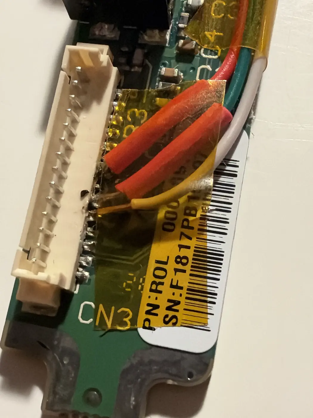
CN3’s pitch is tight. Kapton over 8 and 11 before touching 9 and 10. 30 AWG wire with silicone or PTFE insulation, a fine conical tip, no-clean flux, everything pre-tinned, one-second touches. A phone camera at 3× zoom is a decent microscope. Twist D+ and D− loosely together, and put Kapton under anything that crosses the board edge, because that edge sits against the case.
Before power
Beep every wire end to end. Then check CN3 9 and 10 to 8, 11 and 7, and to each other. Nothing should beep. A short chirp from 5 V to ground that fades is a capacitor charging, which is fine.
Then the whole path through a cable. A-plug contacts to CN3: 5 V to 7, GND to 14, D+ to 9, D− to 10. Neither data contact to ground.
It doesn’t switch on when you plug it in
Screw the ports board down before testing. Loose on the bench, mine wouldn’t switch on at all.
Plugged in, nothing. No power-up, no light. Earlier in the repair it had woken up the moment the cable went in, so this looked like I’d killed it. I was pricing a new ports board.
Switch it on with the button.
System Information → USB: Seaboard RISE, 12 Mb/s. MIDI Studio sees it. Dashboard sees it. It charges over the cable too.
Lock it down
I didn’t epoxy it. Kapton over everything, wires taped flat along the board.
The cracked traces don’t matter any more. The strip still flexes, though, and now it flexes against the new joints on the jack legs. If they ever go, two-part epoxy (UHU plus endfest 300) along the strip is the next step. Until then: an angled cable, and nothing hanging off the plug.
Techbyte001
Techbyte001 got there first, with a jack that had torn its pads clean off. Same idea: wires from the jack straight to the ports-board connector. Their photos number CN3 from the other end, so their pin n is my pin 15 − n. Their #5 and #6 are my 10 and 9. Their leg order matches what I measured, and I should have believed it sooner.