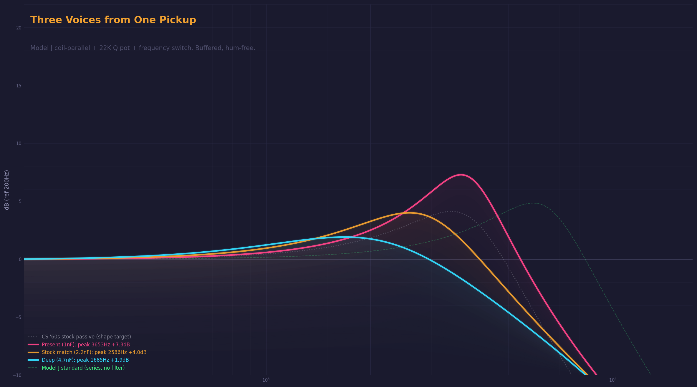
Three curves from one pickup. Same coils, same pot, different cap. The dotted gray is a stock Fender CS ’60s through a passive circuit with a cable. The orange curve matches its shape. Hum-free, buffered, with the Q profile of a loaded single-coil.
The problem
A standard tone pot rolls off treble by shunting high frequencies to ground through a capacitor. The pot’s resistance controls how much gets through. This works well when the pickup impedance is high (4-5H inductance): the pot has leverage because it’s a significant fraction of the total circuit impedance.
The DiMarzio Model J has 4-conductor wiring that allows coil-parallel mode. Both internal coils run in parallel instead of series. Inductance drops from 4.7H to 1.175H. The resonant peak shoots up to 9.1kHz. Brighter than any single-coil in the 30-pickup database.
But at 1.175H, a standard 500K tone pot gives 1.8dB of sweep. The pickup impedance is too low for the pot to grab hold of.
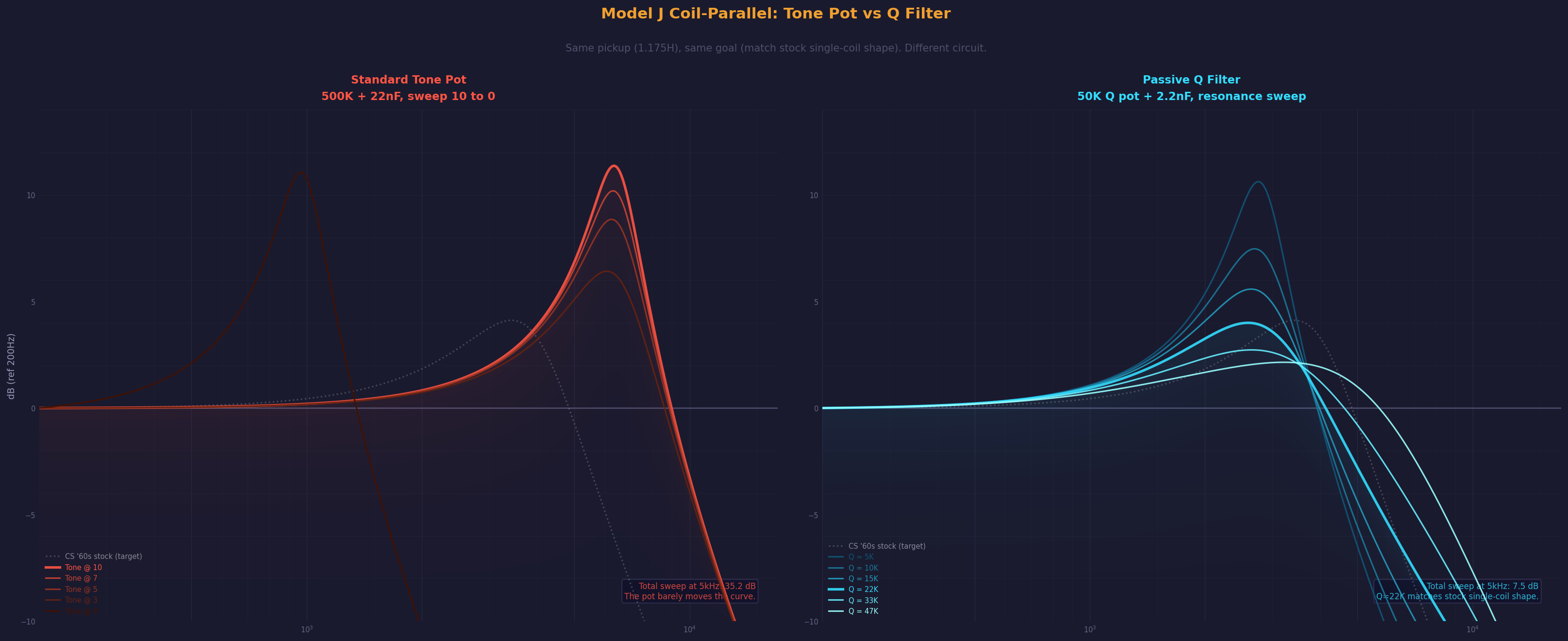
Left panel: a 500K tone pot from 10 to 0. The curves stack on top of each other. The pot is effectively dead.
Right panel: the same pickup through a passive Q filter (50K pot + 2.2nF cap in series to ground). The curves spread across 7.5dB. At Q=22K, the response matches the stock CS ’60s passive shape. The filter does what the tone pot can’t.
How it works
A tone pot is a variable resistor with a cap to ground. The pot sets how much signal bleeds through the cap. It’s a treble rolloff.
The Q filter is different. A fixed cap and a variable resistor in series to ground. The cap sets which frequency range gets loaded. The pot sets how hard. Instead of rolling off treble, it controls how much the pickup’s resonant peak rings.
Turn it down: heavy damping, flat response, studio-clean. Turn it up: the peak emerges, the pickup starts to ring like a loaded single-coil.
At 22K with a 2.2nF cap, the Model J coil-parallel response matches the shape of a stock CS ’60s through 250K pots and a cable. Same peak height (+4.0dB vs +4.1dB). Similar Q (0.95 vs 1.13). Hum-free, buffered, no cable loading.
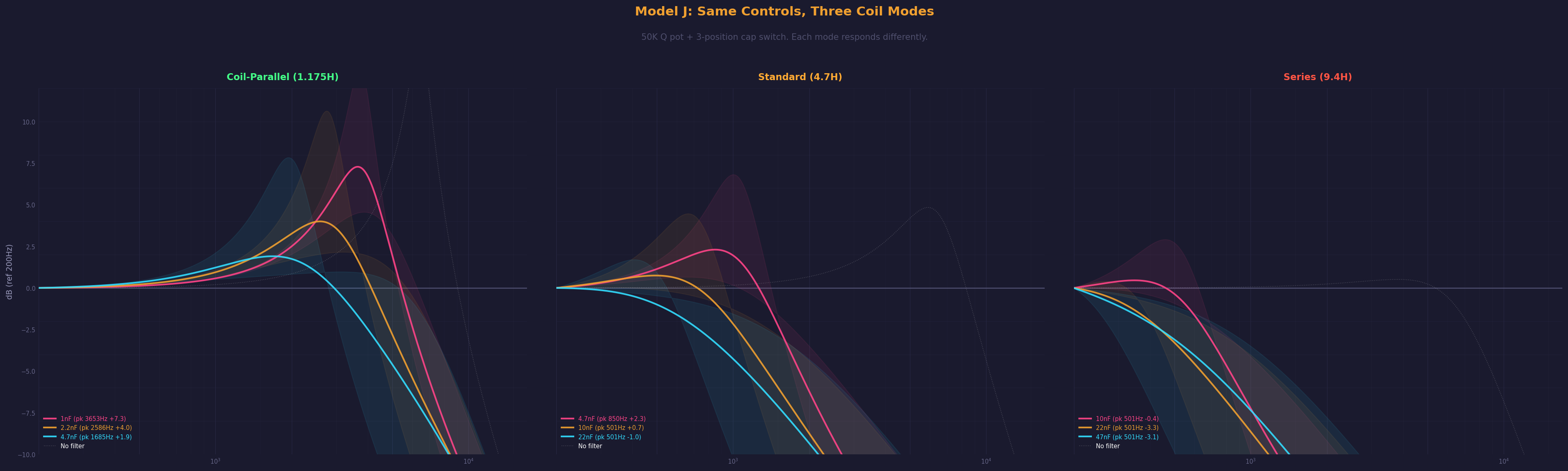
Three modes from one switch
The Q filter works at any impedance if you scale the cap to match. Higher inductance needs a larger cap. A single mode switch gangs the coil routing and the cap selection together.
| Mode | Inductance | Cap | Peak @ Q=22K | Sweep range |
|---|---|---|---|---|
| Coil-parallel | 1.175H | 2.2nF | 2586Hz +4.0dB | 7.5dB |
| Standard | 4.7H | 10nF | ~1kHz +0.7dB | 17dB |
| Series | 9.4H | 22nF | sub-500Hz -3.3dB | 20dB |
The shaded regions show the full Q pot sweep. Every mode has massive range from a single 50K pot. The cap switch matches the filter to the impedance so the pot works musically everywhere.
The Q sweep
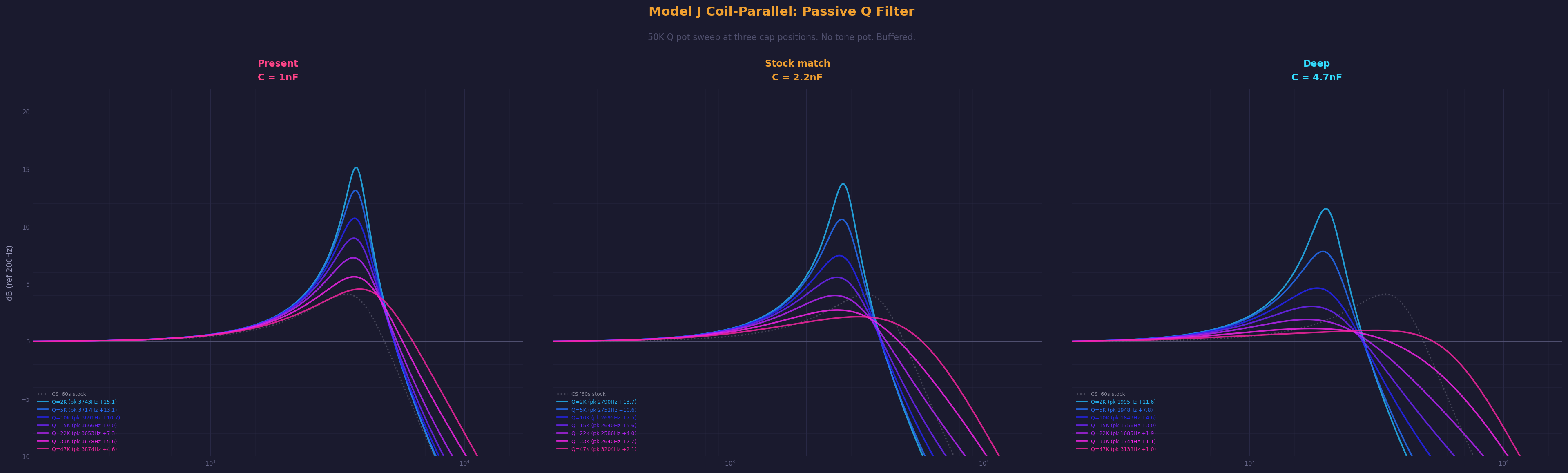
Three panels, one per cap position. The rainbow of curves is the Q pot from 2K (flattest) to 47K (most resonant). The CS ’60s stock passive is the gray dotted reference in each panel.
The sweet spot for matching the stock single-coil shape is around 22K. Below that, the response flattens toward a studio reference signal. Above it, the peak sharpens and the pickup starts to ring. Both extremes are musically useful, and the transition is smooth.
The loading chart

This is how the circuit was designed. The cyan curve is the best pure-resistive load (15K to ground). It’s too flat. The orange curve is 22K + 2.2nF. The R+C combination creates frequency-selective loading: the cap blocks low frequencies (preserving bass and low mids) while the resistor damps the resonant peak region. The result matches the stock single-coil shape with a distance of 1.63 RMS, compared to 3.60 for the best pure-R match.
The controls
Three knobs, one switch.
| Control | Part | What it does |
|---|---|---|
| Volume | 500K audio taper | Master volume |
| Blend | MN250K dual-gang | Neck/bridge mix |
| Q | 50K linear pot | Filter resonance (flat to resonant) |
| Mode | 4P3T rotary switch | Coil wiring + cap selection |
The mode switch has three positions:
| Position | Coils | Cap | Sound |
|---|---|---|---|
| Up | Coil-parallel (1.175H) | 2.2nF | Bright, open, stock Q match |
| Center | Standard series (4.7H) | 10nF | Mid-forward, ceramic snap, the “regular J-bass” sound |
| Down | Both-pickup series (9.4H) | 22nF | Deep, P-bass territory |
No tone pot. The Q filter replaces it. The control is resonance, not rolloff.
The signal chain
Model J pickups (4-conductor)
  -> Mode switch (4P3T):
       coil routing + cap selection
  -> Blend (MN250K)
  -> Volume (500K)
  -> Q filter (50K pot + switched cap)
  -> Buffer (2N5457 JFET)
  -> TRS out (phantom powered)
  -> Junction box -> UCX II
The buffer is required. Without it, cable capacitance loads the pickup directly and the filter does something completely different.
Why this is different
Standard bass tone controls are treble rolloffs. Turn down, it gets darker. The Q filter controls resonance. Turn down, it gets flatter. Turn up, it gets more characterful. The peak frequency stays the same (set by the cap), only the intensity changes.
Active filter preamps (Alembic, Wal, ACG/John East, Lusithand) do the same thing with op-amps and gain stages. They can boost as well as cut, sweep the frequency continuously, and drive any cable length. They cost $150-300 and need a battery.
This circuit does a subset of what those preamps do, passively, with a $2 pot and three caps. It can’t boost and it can’t sweep the frequency continuously. But it matches the stock single-coil Q profile, which none of those active preamps are specifically designed to do.
Nobody’s documented this topology for bass or guitar. Coil-parallel mode lowers the impedance enough for a passive filter to work. The R+C shunt provides frequency-selective Q damping. The buffer isolates the circuit from the cable. The combination hasn’t been documented. Web research confirms it.
Parts
| Part | Spec | Cost estimate |
|---|---|---|
| DiMarzio Model J DP123 (pair) | 4-conductor, ceramic split-coil | ~$140 |
| Volume pot | CTS 500K audio taper | ~$12 |
| Blend pot | MN250K dual-gang, center detent | ~$15 |
| Q pot | 50K linear taper | ~$8 |
| Mode switch | 4P3T rotary (Elma, C&K, or Alpha) | ~$15 |
| Filter cap 1 | 2.2nF film | ~$0.50 |
| Filter cap 2 | 10nF film | ~$0.50 |
| Filter cap 3 | 22nF film | ~$0.50 |
| Buffer JFET | 2N5457 (TO-92) | ~$4 |
| Buffer components | 1M + 4.7K resistors, 2x 10uF caps | ~$3 |
| Output jack | Switchcraft 12B (TRS) | ~$8 |
Total electronics cost (excluding pickups): ~$65
Open questions
The blend pot interaction with coil-parallel mode hasn’t been simmed. At 1.175H the blend pot’s impedance is more significant relative to the pickup. If the MN250K loads the parallel mode differently than series, the filter response changes with blend position. This needs bench verification before the circuit is final.
The 4P3T rotary switch may need a new hole in the control plate. Cap values are sim-derived starting points. Linear taper on the Q pot is the starting spec.
Companion to the standard harness and the pickup shootout that found the tone pot dead at 1.175H. This build is the fix. Supersedes the switched-load approach in the wiring guide’s Advanced section.