Circular Labs Mobius is a free AU/VST looper plugin. Eight parallel loops. Quantized switching. Half speed, reverse, multiply. Everything the Echoplex promised but in software. Ethan Tufts at Strymon performs as State Shirt with Mobius running inside Ableton. Full arrangements, built live.
The problem is controlling it. Hands on the guitar. You need your feet. Nobody sells a MIDI foot controller for Mobius.
So here’s one.
The idea
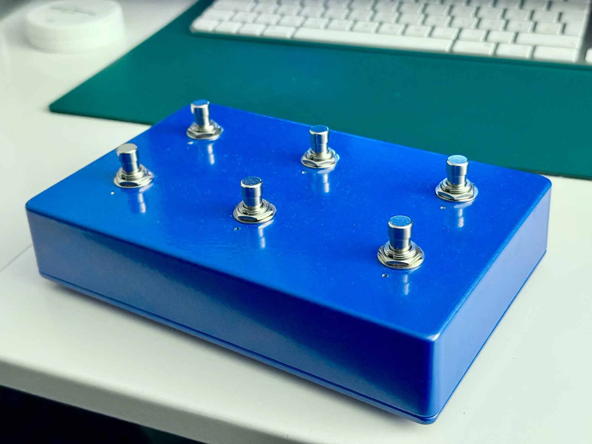
Six footswitches. Each does three things: tap, double tap, hold. Up to 18 MIDI messages from a box the size of a paperback.
Expression pedal for loop feedback. RGB LEDs for state: recording, playing, overdubbing, reversed. Glance down and you know.

Bottom row: record, overdub, mute. The core workflow. Top row: undo, multiply, reverse. Double tap any top row switch to jump between four loops.
Parts
EU suppliers. Most of the cost is the Teensy and the switches.
| Part | Spec | Qty | Source | Price |
|---|---|---|---|---|
| Microcontroller | Teensy 4.0 (without headers) | 1 | BerryBase / Exp-Tech | ~€30 |
| Footswitches | Momentary Soft-Touch SPST-NO (Banzai SKU 41888) | 6 | Banzai Music | €30 |
| Enclosure | DC-DD Diecast Aluminum 188x120x37mm | 1 | Banzai Music | €12 |
| LEDs | WS2812B strip, cut to 6 individual LEDs (SEZO 1m 60LED) | 1 | Amazon DE | €9 |
| USB panel mount | MEIRIYFA USB-B D-type female to USB-A female | 1 | Amazon DE | ~€7 |
| Internal USB cable | PAXO 30cm USB-A to Micro-B | 1 | Amazon DE | ~€6 |
| Expression jack | 6.35mm TRS stereo panel mount | 1 | Banzai Music | €2 |
| Resistors | 470 ohm x1, 10K ohm x1 | 2 | on hand | – |
| Wire | 22-24 AWG stranded, multiple colors | – | on hand | – |
| Standoffs | M3 nylon for Teensy mounting | 4 | on hand | – |
~€95 total.
Alternative suppliers
Reichelt, Mouser EU, Thomann carry most of these. The footswitches are hardest to source. Soft touch momentary, not clicky. The Banzai ones are quiet under bare feet or shoes.
Tools
Soldering iron, solder, wire strippers, multimeter. Drill bits: 12mm (switches), 5–8mm (LED holes), 10mm (TRS jack), 24mm (USB-B panel mount). Deburring tool. Hot glue gun for LED mounting.
Wiring

Pin assignments
| Teensy Pin | Connected To | Notes |
|---|---|---|
| Pin 1 | WS2812B data in | Through 470 ohm resistor |
| Pin 2 | SW1 (Record) | INPUT_PULLUP, other leg to GND |
| Pin 3 | SW4 (Undo) | INPUT_PULLUP, other leg to GND |
| Pin 4 | SW5 (Multiply) | INPUT_PULLUP, other leg to GND |
| Pin 5 | SW6 (Reverse) | INPUT_PULLUP, other leg to GND |
| Pin 6 | SW2 (Overdub) | INPUT_PULLUP, other leg to GND |
| Pin 7 | SW3 (Mute) | INPUT_PULLUP, other leg to GND |
| Pin 14 (A0) | Expression pedal tip | 10K pulldown to GND |
| 3V3 | Expression pedal ring | Reference voltage |
| VUSB | WS2812B VCC | 5V power for LEDs |
| GND | Common ground bus | All grounds meet here |
Pin numbers don’t follow switch layout. Pin 2 is SW1 but Pin 3 is SW4. I wired them in logical order on the Teensy and a different order in the enclosure. The firmware remaps.
Physical layout in the enclosure
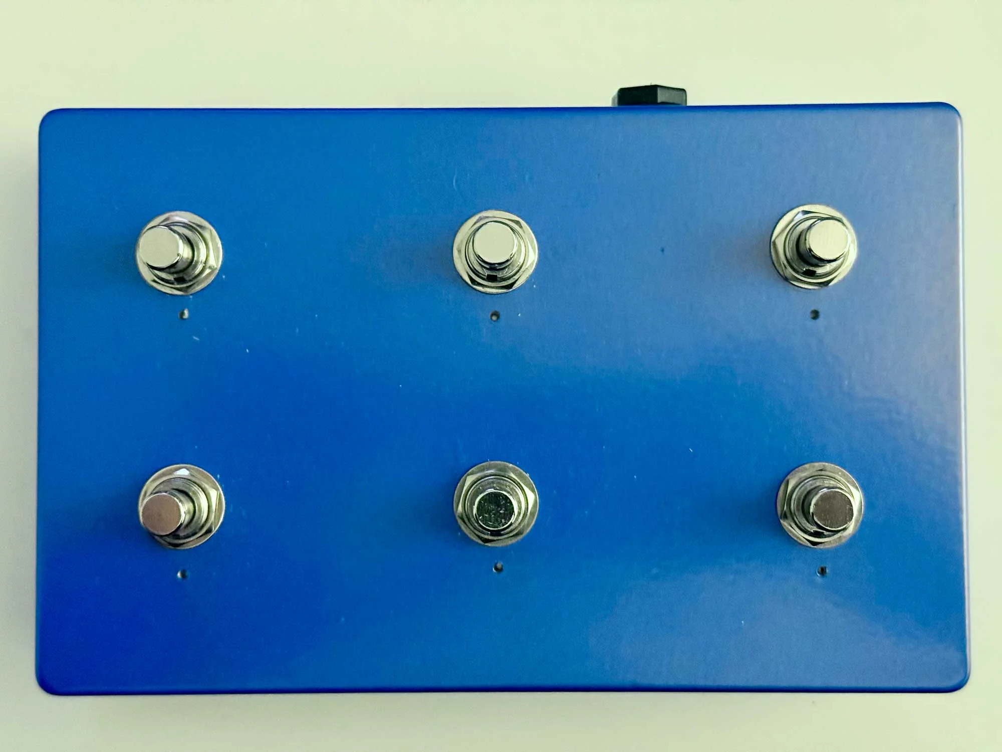
BACK ROW (30mm from top edge)
   SW4 (Pin 3)     SW5 (Pin 4)     SW6 (Pin 5)
   Undo            Multiply        Reverse

FRONT ROW (80mm from top edge)
   SW1 (Pin 2)     SW2 (Pin 6)     SW3 (Pin 7)
   Record          Overdub         Mute

TOP LEFT: USB-B panel mount
TOP RIGHT: TRS expression jack
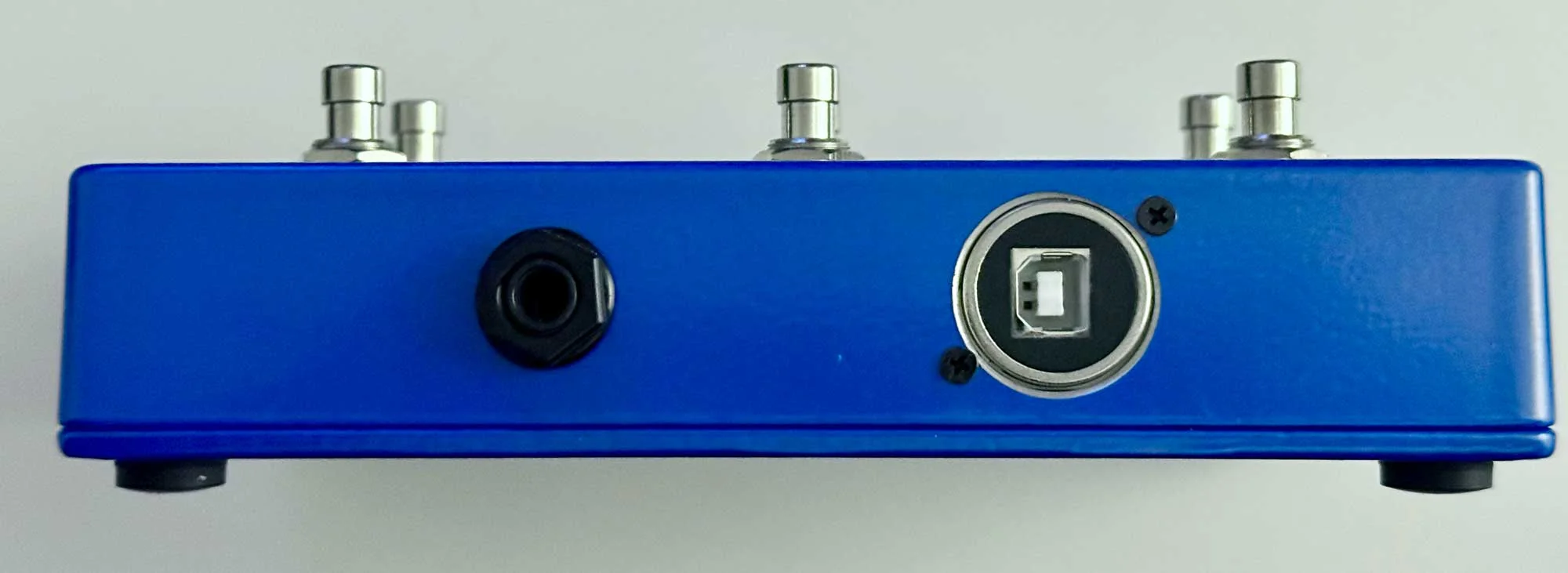
Connectors
Both mount on the front face. USB-B left, expression jack right. Below the top edge. Visible from the front, barely peeking out from above.
LED chain wiring
Cut six individual LEDs from a WS2812B strip. Snake pattern: left to right across the top row, right to left across the bottom.
Data in → [LED0] → [LED1] → [LED2]
                                ↓
          [LED5] ← [LED4] ← [LED3]
Data order reverses on the bottom row. The firmware remaps:
const uint8_t SW_TO_LED[] = {5, 0, 1, 2, 4, 3};
Mount LEDs in drilled holes above each switch. Hot glue works fine. Keep the data wire runs short.
Ground scheme
Solder lug bolted inside the enclosure. Scrape the paint for bare metal contact. All grounds run to this single lug:
- 6 switch grounds
- TRS jack sleeve
- Expression pedal 10K pulldown resistor
One wire from the lug to the Teensy GND pin. Star ground. No loops. No noise.
Expression pedal wiring
Standard TRS convention:
- Tip goes to Pin 14 (A0) on the Teensy
- Ring goes to 3V3
- Sleeve goes to GND
10K pulldown from Tip to GND so the pin reads zero with no pedal connected. Parallel, not series.
Pedal works backwards? Swap Ring and Sleeve.
USB connection
USB-B D-type panel mount on the outside. Short USB-A to Micro-B cable to the Teensy inside. More reliable than a single adapter cable, and USB-B looks like it belongs on audio equipment. 24mm hole, D-type flange with screws.
Firmware
Two files. Clone the repo or drop them into footswitch_controller in your Arduino sketchbook.
config.h is pin assignments, MIDI CC mapping, gesture timing, LED colors. Change this if your wiring differs from mine. footswitch_controller.ino is the gesture state machine, MIDI I/O, and LED animation engine.
Arduino IDE setup
- Install Arduino IDE
- Install Teensyduino
- Board: Teensy 4.0, USB Type: MIDI
- Libraries: Bounce2, Adafruit NeoPixel
How the gestures work
On release, the firmware waits 300ms. Second tap arrives, double tap fires. Nothing comes, single tap fires. Hold past 500ms fires immediately, no waiting.
Each switch runs its own state machine. No blocking. All six processed every loop cycle.
300ms: fast enough you don’t feel the delay, slow enough double taps register. I tried 200 and kept misfiring. 400 felt sluggish.
LED feedback
Not decoration. Information.
Bottom row: warm tones. Amber playing, deep red recording, warm white idle. Top row: cold tones. Ice blue active, cool white at rest.
The split came from the enclosure. Metallic blue aluminum. Warm amber and ice blue look right against it. Green for “playing” looked like a cheap toy.
Modes: solid, dim, blink (three speeds), sine wave pulse (10–100% brightness), 150ms tap flash. Global brightness at 50/255. For glancing at in a dim room.
MIDI mapping
Tap (primary)
| Switch | CC | Function |
|---|---|---|
| Record | 1 | Start/stop recording |
| Overdub | 2 | Add layers |
| Mute | 3 | Silence loop, keep it running |
| Undo | 4 | Step back one layer |
| Multiply | 5 | Extend loop length |
| Reverse | 6 | Toggle reverse playback |
Double tap (secondary)
| Switch | CC | Function |
|---|---|---|
| Record | 11 | Clear loop |
| Overdub | 12 | Half speed (the Ed O’Brien trick) |
| Mute | 13 | Select Loop 4 |
| Undo | 14 | Select Loop 1 |
| Multiply | 15 | Select Loop 2 |
| Reverse | 16 | Select Loop 3 |
Hold (modifier)
Three switches mapped. Record, Undo, and Multiply hold slots reserved.
| Switch | CC | Function |
|---|---|---|
| Overdub | 22 | Insert |
| Mute | 23 | Pause |
| Reverse | 26 | Speed toggle |
Half speed on Overdub. The Ed O’Brien trick. Record a loop, drop it half speed. Falls an octave, stretches to twice the length. Layer on top.
Top row double taps jump between loops: Undo → Loop 1, Multiply → Loop 2, Reverse → Loop 3. Loop 4 on Mute because the top row was full.
Expression pedal
CC 7, feedback. Full toe: infinite repeats. Full heel: decay.
Mobius configuration
Binding XML
Configuration → Bindings. Import mobius_bindings.xml or add bindings manually with Capture.
<BindingSet name="Footswitch v3" ordinal="0">

  <!-- TAP (CC#1-6) -->
  <Binding name="Record" trigger="control" channel="1" value="1"/>
  <Binding name="Overdub" trigger="control" channel="1" value="2"/>
  <Binding name="Mute" trigger="control" channel="1" value="3"/>
  <Binding name="Undo" trigger="control" channel="1" value="4"/>
  <Binding name="Multiply" trigger="control" channel="1" value="5"/>
  <Binding name="Reverse" trigger="control" channel="1" value="6"/>

  <!-- Expression pedal -->
  <Binding name="feedback" trigger="control" channel="1" value="7"/>

  <!-- DOUBLE-TAP (CC#11-16) -->
  <Binding name="Clear" trigger="control" channel="1" value="11"/>
  <Binding name="Halfspeed" trigger="control" channel="1" value="12"/>
  <Binding name="SelectLoop" trigger="control" channel="1" value="13" arguments="4"/>
  <Binding name="SelectLoop" trigger="control" channel="1" value="14" arguments="1"/>
  <Binding name="SelectLoop" trigger="control" channel="1" value="15" arguments="2"/>
  <Binding name="SelectLoop" trigger="control" channel="1" value="16" arguments="3"/>

  <!-- HOLD (CC#21-26) -->
  <Binding name="Insert" trigger="control" channel="1" value="22"/>
  <Binding name="Pause" trigger="control" channel="1" value="23"/>
  <Binding name="SpeedToggle" trigger="control" channel="1" value="26"/>

</BindingSet>
Manual binding with Capture
One at a time:
- Open Mobius, Configuration, Bindings
- Select or create “Footswitch v3” binding set
- Click a function in the left panel (e.g. Record)
- In the Trigger section, set Type to Control, Channel to 1
- Check Capture, then press the corresponding footswitch
- The CC number fills in automatically
- Leave Release unchecked
- Click Save
Session settings
Without quantization, loops drift.
| Setting | Value | Why |
|---|---|---|
| Sync Source | Host | Logic Pro is the tempo master |
| Quantize | Loop | Functions execute at loop boundary |
| Switch Quantize | Loop | Loop switching waits for boundary |
| Subcycles | 4 | Loop divided into 4 sections |
| Empty Loop Action | Copy Timing | New loops inherit length from current |
| Empty Track Action | Copy Timing | Same for new tracks |
| Max Undo | 10+ | Keep plenty of undo layers |
| Mute Mode | Continue | Loop keeps running when muted |
Build sequence
This order avoids rework.
- Test on breadboard first. Wire two switches and two LEDs. Verify MIDI messages appear in a MIDI monitor. Verify LEDs respond. Do not touch the enclosure until this works.
- Solder wires to the Teensy. No headers. Direct solder. This keeps the profile low inside the enclosure.
- Test all six switches and all six LEDs on breadboard. Verify every CC number, every LED index.
- Drill the enclosure. Pilot holes first. 12mm for switches, 5-8mm for LED holes, 10mm for TRS, 24mm for USB-B. Deburr everything.
- Mount panel components loosely. Switches, TRS jack, USB mount. Do not tighten yet.
- Install the ground lug. Scrape paint, bolt it down, check continuity to enclosure.
- Mount the Teensy on nylon standoffs inside the enclosure.
- Wire the ground bus. All switch grounds, TRS sleeve, and pulldown resistor to the solder lug.
- Wire switches to their Teensy pins.
- Wire the LED chain with the 470 ohm resistor on the data line.
- Wire the expression jack. Tip to A0, Ring to 3.3V, Sleeve to ground bus.
- Connect USB panel mount to Teensy via the internal cable.
- Test everything before closing. Every switch, every LED, the expression pedal. Use a MIDI monitor.
- Tighten and close.
Things that went wrong
USB-C adapter DOA. Adafruit 4056, USB-C to Micro-B. Zero power passthrough. The USB-B panel mount was the better choice anyway. More robust, standard cables.
3.3V driving 5V LEDs. Datasheet says WS2812B needs 3.5V minimum for logic high. 470 ohm resistor on the data line and short runs made it work. If it doesn’t, add a 74AHCT125 level shifter. I bought one and never needed it.
10ms debounce. Expected to need 20ms. Never saw a double trigger at 10.
What I would do differently
Label the switches. Layout took a week to memorise. An engraved faceplate would help anyone else.
LED diffusers. Raw WS2812Bs are point sources. A frosted cap over each would soften the light.
MIDI DIN output for hardware that doesn’t speak USB.
Everything you need
Parts, wiring, firmware, Mobius configuration. If you build one, or build something better, I’d like to hear about it.